An engineering drawing is a type of technical drawing that is used to convey information about an object. A common use is to specify the geometry necessary for the construction of a component and is called a detailed drawing. Usually, a number of drawings are necessary to completely specify even a simple component.
The drawings are linked together by a master drawing or assembly drawing which gives the drawing numbers of the subsequent detailed components, quantities required, construction materials, and possibly 3D images that can be used to locate individual items. Although mostly consisting of pictographic representations, abbreviations and symbols are used for brevity and additional textual explanations may also be provided to convey the necessary information.
The process of producing engineering drawings is often referred to as technical drawing or drafting. Drawings typically contain multiple views of a component, although additional scratch views may be added to details for further explanation. Only the information that is a requirement is typically specified.
Key information such as dimensions is usually only specified in one place on a drawing, avoiding redundancy and the possibility of inconsistency. Suitable tolerances are given for critical dimensions to allow the component to be manufactured and function.
More detailed production drawings may be produced based on the information given in an engineering drawing. Drawings have an information box or title block containing who drew the drawing, who approved it, units of dimensions, the meaning of views, the title of the drawing, and the drawing number.
History
The technical drawing has existed since ancient times. Complex technical drawings were made in renaissance times, such as the drawings of Leonardo da Vinci. Modern engineering drawing, with its precise conventions of orthographic projection and scale, arose in France at a time when the Industrial Revolution was in its infancy. L. T. C. Rolt’s biography of Isambard Kingdom Brune says of his father, Marc Isambard Brunel, that “It seems fairly certain that Marc’s drawings of his block-making machinery in 1799 made a contribution to British engineering technique much greater than the machines they represented.

For it is safe to assume that he had mastered the art of presenting three-dimensional objects in a two-dimensional plane which we now call mechanical drawing. It had been evolved by Gaspard Monge of Mezieres in 1765 but had remained a military secret until 1794 and was therefore unknown in England.”
Standardization and disambiguation
Engineering drawings specify the requirements of a component or assembly which can be complicated. Standards provide rules for their specification and interpretation. Standardization also aids internationalization, because people from different countries who speak different languages can read the same engineering drawing, and interpret it the same way.
The implication of this is that any drawing using ISO symbols can only be interpreted to ISO GPS rules. The only way not to invoke the ISO GPS system is to invoke national or other standards. Britain, BS 8888 Technical Product Specification has undergone important updates in the 2010s.
Media
For centuries, until the post-World War II era, all engineering drawing was done manually by using pencil and pen on paper or other substrates. Since the advent of computer-aided design (CAD), engineering drawing has been done more and more in the electronic medium with each passing decade. Today most engineering drawing is done with CAD, but pencil and paper have not entirely disappeared.
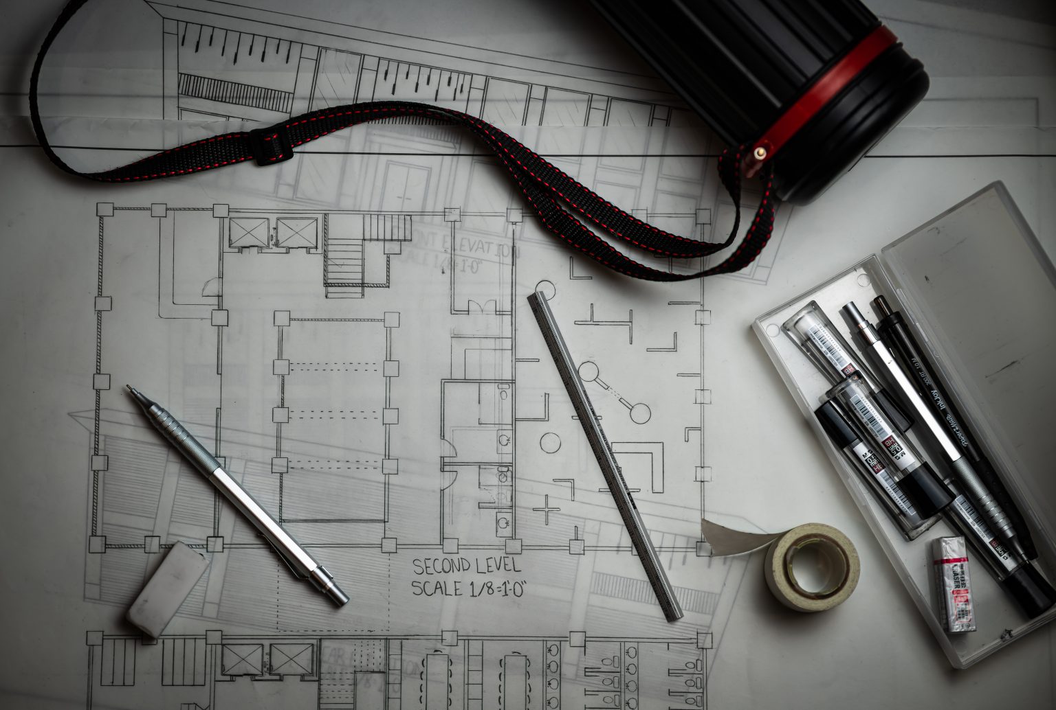
Some of the tools of manual drafting include pencils, pens, and their ink, straightedges, T-squares, French curves, triangles, rulers, protractors, dividers, compasses, scales, erasers, and tacks or push pins. And of course, the tools also include drawing boards (drafting boards) or tables. The English idiom “to go back to the drawing board”, which is a figurative phrase meaning to rethink something altogether, was inspired by the literal act of discovering design errors during production and returning to a drawing board to revise the engineering drawing.
Drafting machines are devices that aid manual drafting by combining drawing boards, straightedges, pantographs, and other tools into one integrated drawing environment. CAD provides their virtual equivalents. Producing drawings usually involves creating an original that is then reproduced, generating multiple copies to be distributed to the shop floor, vendors, company archives, and so on.

The classic reproduction methods involved blue and white appearances whether white-on-blue or blue-on-white, which is why engineering drawings were long called, and even today is still often called, “blueprints” or “bluelines”, even though those terms are anachronistic from a literal perspective since most copies of engineering drawings today are made by more modern methods often inkjet or laser printing that yield black or multicolor lines on white paper. The more generic term “print” is now in common usage in the U.S. to mean any paper copy of an engineering drawing. In the case of CAD drawings, the original is the CAD file, and the printouts of that file are the “prints”.
Systems of dimensioning and tolerancing
Almost all engineering drawings communicate not only geometry but also dimensions and tolerance for those characteristics. Several systems of dimensioning and tolerancing have evolved. The simplest dimensioning system just specifies distances between points. Since the advent of well-developed interchangeable manufacture, these distances have been accompanied by tolerances of the plus-or-minus or min-and-max-limit types.
Coordinate dimensioning involves defining all points, lines, planes, and profiles in terms of Cartesian coordinates, with a common origin. Coordinate dimensioning was the sole best option until the post-World War II era saw the development of geometric dimensioning and tolerancing, which departs from the limitations of coordinate dimensioning (e.g., rectangular-only tolerance zones, tolerance stacking) to allow the most logical tolerancing of both geometry and dimensions and sizes.
What Does the Future Hold?
Engineering drawings are still a big part of an engineer’s job. All in all, making them contributes to about 20% of a design engineer’s work time.
We at Factory are trying to save this time by automating the reading of 3D models for production. This leaves engineers with the task of producing assembly and GD&T drawings only. The purpose is to keep the focus on engineering better products.
The engineering community is seeing this movement as a new trend. But as we all know, taking the whole industry up to a new standard takes a lot of time. Thus, if you still outsource your production to manufacturing companies that need drawings, you must know the basics at the very least.
Leaving room for interpretation creates a situation where your idea may not be executed as planned. And there is nobody else to blame but the author.
So consider this stage of the product development process as an integral part that requires thinking along. Keep thinking in the drawing-room.
We being one of the best colleges in Hyderabad offers aspiring engineering to upscale in innovations and work on a wide range of project and gain vast knowledge on the same. Know more about us here.
Follow us on: Facebook | Instagram | LinkedIn
Also Read: The Importance Of Engineering In The Modern World